


[Transformer] DC resistance experiment
Purpose
In the field: Check the quality of coil connections, coil condition (open circuit or short between coils)
In the factory, DC resistor value to:
+ Calculate losses in the transformer (I 2 R)
+ Calculate the winding temperature during the transformer temperature rise test
+ Used as a standard value for comparison and evaluation when testing in the field
Procedure
· With star-connected windings, the DC resistance is measured between phases and neutral
· With the star-connected winding of an autotransformer, the high-side dc resistance is measured between the high-voltage terminal (HV terminal) and the voltage input (IV terminal), then between the voltage input and neutral
· With delta-connected windings, the dc resistance is measured between phase pairs (AB; BC; CA).
· Temperature conversion: Purpose to compare resistance values under the same conditions
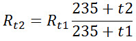
t1 – coil temperature during testing; t2 – conversion/reference temperature
Method
1. Current-pressure method
1. Current – voltage method (Refer to IEEE standard C57.152)
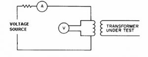
The current-voltage (VA) method, also known as the 4-wire Kelvin diagram method, is the most commonly used method for measuring transformer winding resistance. This measurement method is performed by applying a direct current and measuring the voltage value again. Then, apply Ohm's law (R = U/I) to calculate the resistance value. The values of current and voltage are measured simultaneously through the following wiring diagram
NOTE: To minimize measurement errors, the following measures should be taken:
1. a) Measuring devices or winding resistance meters should have a range wide enough to permit readings of values formed over the full range or in any case over 70% of the measuring range.
2. b) The polarity of the magnetic core must be kept constant throughout the resistance measurement process.
Note—Reversing the magnetic direction of the magnetic core may cause a change in the time constant and erroneous display results.
1. Voltage measuring leads and current measuring leads must be independent of each other and connected as close as possible to the ends of the coil to be measured. This avoids the resistance of the current probes and contact points, and the resistance of the extension wires from appearing in the coil resistance measurement results.
2. The current used for these measurements should not exceed 15% of the rated current in the transformer winding. This avoids heat generation and possible changes in winding resistance.
3. Because of the inductance of the coil, fixing the dc current for a long time can sometimes result in unstable current and voltage values.
Readings should not be recorded until current and voltage have reached stable values. This value can be obtained more quickly by using a dc source specifically designed for saturated inductive loads.
2. Bridge method
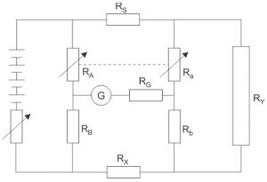
The principle of the Bridge method is to compare an unknown resistor with a known resistor. When current flows through the balanced bridge circuit (galvanometer G shows 0 value). The resistance is calculated as follows:
R X = R S (R A /R B ) where:R A = R a ; R B = R b
Evaluate
The results are often interpreted based on comparison of individual measurements on each phase of a Y terminal or between pairs of poles in a ∆ terminal. Comparisons can also be made with original factory data.
Comparing at the same temperature, the resistance value difference between phases is within 2% and can be accepted within 5%.