


[Transformer] Dielectric loss test
General
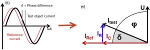
With an ideal capacitance without any losses, the phase difference (φ) between the current through the capacitance and the applied voltage differs by exactly 90 o . In reality, this phase difference angle is always less than 90 o due to dielectric loss. The angle δ = 90 – φ is called the dielectric loss angle
Dielectric losses in insulation are caused by:
· Movement of charged particles.
· Movement of ions and electrons.
· Polarizing effect.
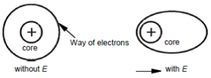
Figure 1: Polarization effect of electrons in an electric field
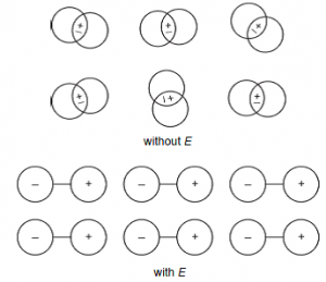
Figure 2: Polarization effect of ions in an electric field
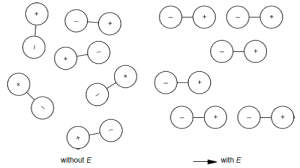
Figure 3: Polarization effect of dipole molecules in an electric field
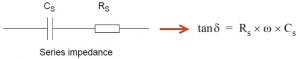
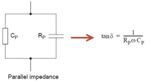
Dielectric loss measurement diagrams are divided into two types
· Series diagram: Characterize bias loss in transformer
· Parallel diagram: Characterizes the inductor loss in the transformer
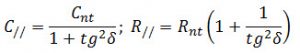
When converting a series diagram to a parallel diagram or vice versa, the resistance and capacitance parameters are calculated using the conversion formula.
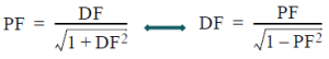
Because the dielectric loss angle and the power factor angle are complementary. Therefore, when measuring the dielectric loss coefficient, we can also convert it to the power coefficient and vice versa as follows:
Purpose
· Determine the insulation quality of the dielectric, the degree of aging, moisture, and contamination of the MBA oil during operation.
Limit
· Required for 35kV transformers with capacity of 10MVA or more
· MBA 110kV or higher regardless of capacity
Method
1. Schering bridge method
The method of measuring capacitance (Capacitance_C) and dielectric loss (Dissipation Factor_DF) was first published by Schering in 1919 and began to be used in 1924.
Schering bridge diagram:
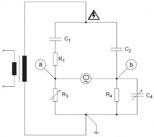
Include:
+ Variable resistor R3
+ Variable capacitance R4
+ Sample capacitor C2
+ Measurement object: C1 & R1
The bridge circuit is balanced when:
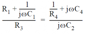
Solve the above circuit to find the real part, imaginary part and loss value as follows:
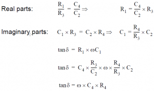
The outstanding advantage of the Schering bridge method is that the calculated values of dielectric loss are not related to current parameters or source voltage. Therefore, the accuracy of measurement results does not depend on the power supply but depends on the accuracy level of many other quantities such as sample capacitor, variable resistance, variable capacitance, electrometer (balance indicator).
2. Direct measurement method of current
The dielectric loss factor is measured by comparing the test object with a sample capacitance (purely capacitive ideal capacitor).
Measuring circuit diagram:
Apply any voltage (the larger the value, the more accurate it is, depending on the ability to generate voltage, the tolerance of the test object and the sample capacitor) on the test object and the sample capacitor (connected in parallel). Measure and compare the current flowing through those two branches (I Ref and I Test ).
· The phase difference angle between the two currents (I Ref and I Test ) is the dielectric loss angle δ
Capacitance value is measured by dividing the applied voltage by the current I Test ( ignoring the resistance R Test has a very small value compared to ZC Test )
The results are measured directly, not through variable resistance or capacitance quantities. Therefore, the measurement results are more accurate than the Schering bridge method, the accuracy depends on the sample capacitor and measuring device.
Evaluate
Compare the results with NSX converted to the same temperature, the dielectric loss value must not be greater than 30% of the measured results when leaving the factory or the previous measurement.
· If the tan δ measurement results in all cases are less than 1% at a temperature of 20 o C, it is considered good and does not need to be compared.
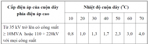
· If the MBA does not have an initial value, you can refer to the maximum allowable value according to the following table:
References
1. CP TD1 reference manual [OMICRON]
2. TANDO 700 user manual [OMICRON]